Background & Motivation
Two months ago, I began learning how to play Electric Guitar; It was simultaneously one of the most fun and frustrating experiences I have ever had. Very reminiscent of 2D Fighting Games! I am only just now getting comfortable enough to attempt to learn how to play songs that I actually enjoy; However, I quickly realized that while I might have gotten a steal for the guitar, I got robbed out of my socks for that modifier.. The amp that came with it is terrible; it has a bunch of static, and the cord is not properly toleranced so it doesn't plug in properly in half the time. Rather than buying an off-the-shelf replacement, however, I decided to take matters into my own hands and design a custom pedal and amplifier system from scratch in KiCad. After all, I refuse to waste my money on an amplifier if I don’t have to- even if the cost is learning a whole bunch of PCB Design.
Power Subsystem & Initial KiCad Design
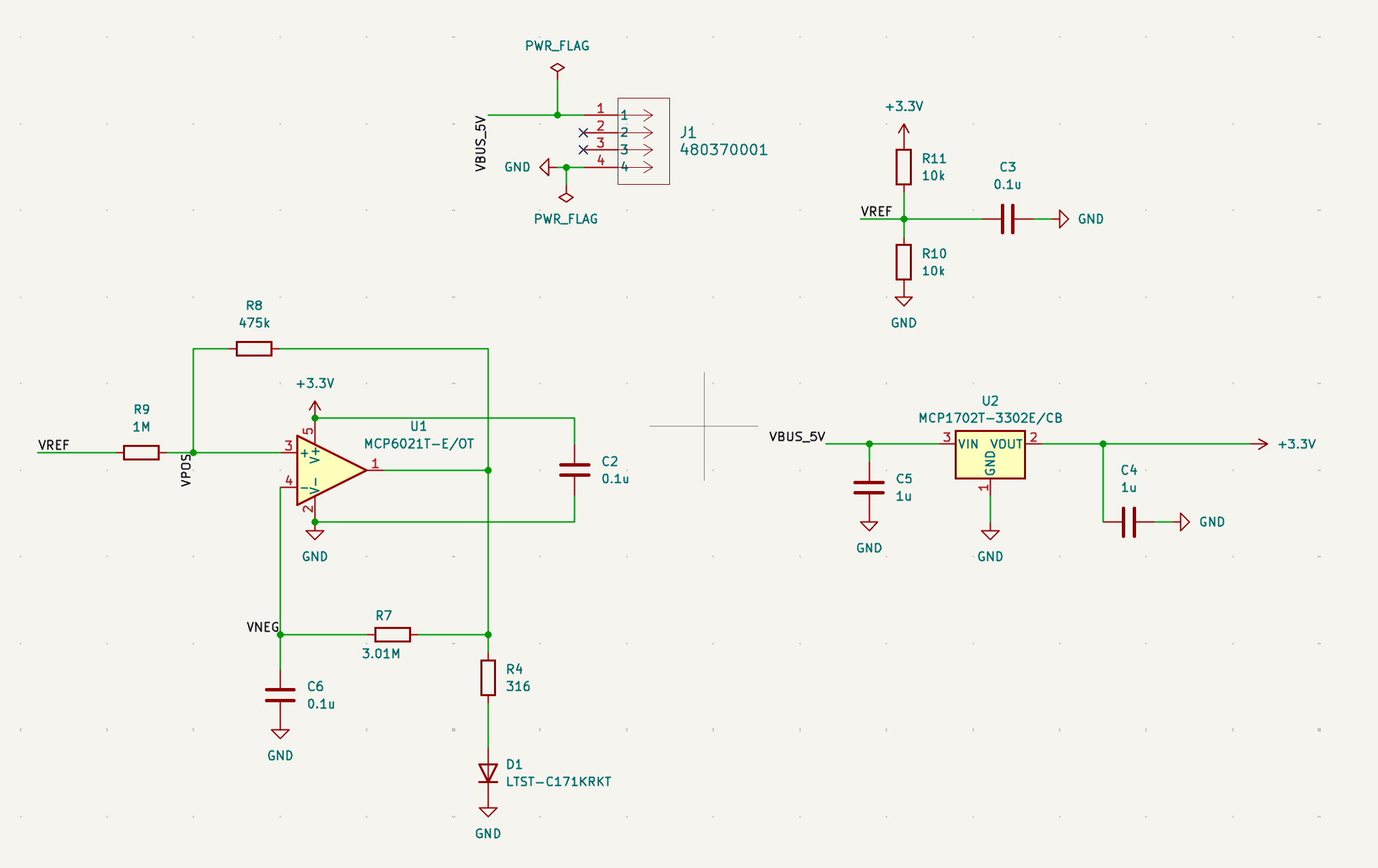
To kick off the project, I decided to start off small by designing the power supply- a 5V USB-C powered LED Flasher circuit- as it seemed like the easiest thing to do. I soon found out it’d be anything but.
Despite appearing straightforward on paper, translating a basic power supply and timing circuit into a functional PCB presented a steep learning curve. Working in KiCad required learning the nuances of schematic capture, footprint assignment, and board-level design rules.
Debugging, Tolerances & Simulation Challenges
The design process quickly proved more demanding than anticipated. In early board iterations, my physical layout clearances and manufacturing tolerances were far too tight, creating routing bottlenecks and risking potential shorts. Concurrently, my SPICE circuit simulations in KiCad were returning incorrect voltage waveforms, which took significant troubleshooting to trace back to multiple routing and net connections mistakes in the schematic.
Overcoming these hurdles involved systematically re-checking netlists, adjusting component spacing, widening power trace clearances, and correcting routing errors. Resolving these issues brought the simulation outputs in line with expected behavior and yielded the clean, fully validated board design you see pictured above.
Results & Future Roadmap
Completing the 5V USB-C power stage and LED status circuit established a solid, working foundation for the overall pedal project. More importantly, overcoming the initial layout and simulation roadblocks provided vital practical experience in hardware design rule check (DRC) workflows and physical board geometry.
With a reliable power supply baseline finished, the next phases will focus on designing the core analog overdrive and buffer stages for the pedal, followed by building a clean, low-noise pre-amp circuit to replace the original static-prone amplifier.